�������ƣ��Ϻ�ɽ�Ϻ�����ó����˾
��ϵ�ˣ��ﱦ����������
��ϵ�ֻ���
�̶��绰��
��ҵ���䣺sh@51082245.com
��ϵ��ַ���Ϻ��б�ɽ��½��·678Ū60��
�ʱࣺ201907
��ϵ��ʱ����˵�������ܰ������Ͽ����ģ�лл��
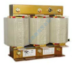
INA/INR 5-100 kvar REACTOR FOR STANDARD CAPACITOR BANK
Description
INA/INR reactors are designed to work in supply systems with a high level of harmonic distortion in such a way that they allow a safe and reliable service of the power factor correction equipments. Reactors are connected in series with power capacitors, forming a resonant circuit conveniently detuned, so that, the whole unit has an inductive impedance at the frequencies of all harmonics in the installation.
These reactors are specially designed to work in series with FMLF capacitors.
Technical Characteristics
Tensi��n nominal red/ Rated voltages of the main ........ 230 / 440 V
Frecuencia/Frequency ........................................................ 50 Hz - 60 Hz
Tensi��n nominal de los condensadores/ ......................... 260 / 460 V
Rated voltages of the capacitors
Tipo de filtro/ Filter type ................................................... Baja sintonizaci��n/Low tuning
Frecuencia resonancia/Resonance frequency ............... 189 Hz (7%)
Tolerancia inductancia/Inductance tolerance ................ �� 3%
M��xima sobrecarga de arm��nicos/ ............................... 0.35 In
Maximum harmonics overload
Construcci��n/Construction .................................................. INA: Aluminio/Aluminium
INR: Cobre/Copper
Protecci��n t��rmica/Thermal proteci��n ............................ Por termostato/By thermostat
Nivel de aislamiento/Insulation level .............................. 4 kV
Conexi��n/Connetion ........................................................... INA: Platina de Aluminio/
Aluminium Bus Bar
INR: Bornes/Terminal block
Grado de protecci��n/Degree of protection ................. INA:IP00/INR: IP 20
Categoria de temperatura/ ............................................. Clase F (155oC)
Category of temperature
Instalaci��n/Installation ....................................................... Interior/Indoor
Normas/Standards ............................................................. IEC 60076-6, EN 60076-6
| Part number | Filter | Dimension(mm) |
Weight (kg) |
Losses W |
Capacitor Code |
Price (�) |
||||||
| Qn (kvar) | Un (V) | h | w | d | a | b | FMLF | POLB (7%) | ||||
| INR40057 | 5 | 400 | 165 | 155 | 92 | --- | --- | 6 | 5 | FMLF4606 | POLB46062HD | 195 |
| INR40107 | 10 | 400 | 190 | 180 | 102 | --- | --- | 9 | 10 | FMLF4612 | POLB46125HD | 210 |
| INR40157 | 15 | 400 | 190 | 180 | 112 | --- | --- | 10 | 25 | FMLF4618 | POLB46185HD | 315 |
| INA40207 | 20 | 400 | 174 | 260 | 124 | 20 | 8 | 14 | 76 | FMLF4625 | POLB46250HD | 265 |
| INA40257 | 25 | 400 | 174 | 260 | 124 | 20 | 8 | 14 | 90 | FMLF4631 | POLB46300HD | 280 |
| INA40307 | 30 | 400 | 231 | 290 | 124 | 20 | 8 | 19 | 120 | FMLF4637 | POLB46370HD | 340 |
| INA40407 | 40 | 400 | 231 | 293 | 124 | 20 | 8 | 20 | 145 | FMLF4649 | 2xPOLB46250HD | 350 |
| INA40507 | 50 | 400 | 233 | 310 | 144 | 25 | 10 | 27 | 185 | FMLF4661 | 2xPOLB46300HD | 370 |
| INA40607 | 60 | 400 | 260 | 305 | 146 | 25 | 10 | 31 | 205 | FMLF4674 | 2xPOLB46370HD | 440 |
| INA40807 | 80 | 400 | 280 | 335 | 155 | 35 | 12 | 38 | 235 | FMLF4698 | 3xPOLB46333HD | 500 |
| INA40997 | 100 | 400 | 300 | 338 | 170 | 35 | 12 | 50 | 250 | 2xFMLF4661 | --- | 990 |
Other voltages and frequencies on request.
|
   
|
INR40057 INA40407 INR40107 INA40507 INR40157 INA40607 INA40207 INA40807 INA40257 INA40997 INA40307
������LIFASA��˾��1949����������Ʒ�ʵ��ݵȲ�Ʒ���ڸ��Ƶ�ʹ����õ�������ռ�ݾ������ƣ�����50%�IJ�Ʒ���ڵ�����������أ���Ʒ�����������ʮ������ҡ���Ʒ��������ISO 9000������Ʒ�����������������ݡ���ѹ�������������������������������顢���Ӵ������������ݡ��˲��迹���ݡ���������������Ƶ��·����������Ƶ��ϵ��������մɵ���������г���������۱���ϩ�����������ϱ�Ĥ�����������չ�������
������LIFASA��Ʒ���Ϲ��ʵ繤ίԱ���Ƽ���IEC831-1��IEC831-2�����ѹ660V�����½���ϵͳ������ʽ������������������ LIFASA������ϵ�����ڹ�Ƶ50Hz��60Hz�����ѹ1000V�����µĽ�������ϵͳ���븺�ز����������ϵͳ�Ĺ����������õ������Խ������۱�ϩ��Ĥ���缫�ͽ��ʣ������Ʒ�����������ܣ���ͬʱ���������ᡢ���С����ĵ͵��ŵ㡣���ҵ������ڲ�װ�й�ѹ������װ�á��������������ͷŵ���裬�кܸߵĿɿ��ԺͰ�ȫ�ԡ� ������LIFASA���������ö�����Ƶ�����ʽ��������Ĥ�������ǿ�˵�����Ԫ���Ķ���Ӻ�������ѹ��Ҫ�Ӷ�����˵������Ŀ�ӿ�����ܺͿɿ��ԣ�������Ͷ�������˲���Ԫ���ĵ���������Ӷ���Ч�ӳ���������ʹ��������
��Ʒ�ص㣺
1�� ��˨���߷�ʽ����֤�˽��ߵĿɿ��ȶ���������������������Ҫ��
2�� ��ȫ�ɿ�����ʽ��ѹ�������ṹ������ʽ�ŵ���裬ʹ�ò�Ʒ����ȫ�����ɿ���
3�� ����������Ԫ����ƣ�����ɢ�������ʹ���������������ͣ��ӳ���������ʹ��������ƽ�������ﵽ100,000Сʱ��
4�� ������Ԫ���ý�������Ĥ�����ر�ķ�����ƣ����кܸߵ��������ܣ��������˸߿ɿ��ԵĽӴ�����ѹ��Ҫ��
5�� ��ȫ��Ч�ķ�����ʩ�������������˺���
6�� ����ɿ��İ�װ��ʽ������˹���Ч�ʣ�
7�� ����Բ��������ǣ�����Ư������С�������ʹ�õ������������ҵ��Ʒ����Ƽҵ绯��������Ʒ����Ϊ�ͻ���������ֵ��
8�� ��Ʒ����IEC831-1��IEC831-2���ʱ���GB/T12747-2004���ұ���Ҫ��
��˾���ܣ�
More than 60 years of history
International Capacitors S.A. is a consolidated company in both Spanish and international markets thanks to many years of experience and dedication to what it has been its product par excellence along its history: the capacitor for the electrical installation. With its commercial brand name LIFASA, present in the market for more than 60 years and a constant technical and technological evolution, it has succeeded in getting adapted continuously to the progress and market requirements nowadays.
LIFASA capacitors are present in the market since 1949. More than 50 % are exported to 70 countries in five continents. Capacitors are manufactured according to European and other International Standards. They have obtained large number of certificates and approvals.
60����Ĺ�˾��ʷ
International Capacitors S.A.�����������ʵ�������˾����Ϊһ���ۺ���˾�������ڶ���ľ���ͷ�����ƾ���Ź�˾��չ��ʷ������Ϊ���ĵ�����װϵͳ�еĵ�������Ʒ��Ϊ���������ں����г��ṩ�˴���Խ�ĵ�������Ʒ����������60����ʷ����ҵƷ��LIFASA�ͳ����ĿƼ���չ���������Ѿ��ɹ��صõ���������������Ӧ�г�������
LIFASA��������1949��������������50%�IJ�Ʒ���ڵ������70�����ҡ��������Ǹ���ŷ���������ʱ�����ģ�����˴�����֤������ļ���
Highest quality standards
International Capacitors S.A. has been from its beginnings a pioneering company in the promotion of the quality of its products. Since 1987, it maintains an ISO9000 Quality System periodically audited by international bodies.
At present, it has quintuple certification ISO9001:2008, ISO14001:2004, OSHAS 18001:2007, IEC QC 080000-RoHS and REACH, that guarantees the highest quality standards in its products, while they are manufactured in a way both environmentally friendly and safe and healthy for its workers. It also has energy efficiency certification ISO 50001:2011
All products included in this catalogue fully comply with the requirements of RoHS Directive.
��ߵ�������
International Capacitors S.A.�����������ʵ�������˾�����Ѳ���һ�������������Ʒ�����ij�����˾����1987��������һֱ��ù�����֯�Ͽɵ�ISO9000������ϵ��֤��
Ŀǰ����˾ӵ������Ȩ����֤��ISO9001:2008��ISO14001:2004��OSHAS 18001:2007��IEC QC 080000 RoHS��REACH����ȷ����Ʒ����������������ͬʱ����Ϊ������Ӫ��һ���Ȼ����ְ�ȫ�����Ĺ����������������н�����֤ 50001:2011��
���ֲ��е����в�Ʒ����ȫ����RoHSָ���Ҫ��
Comprehensive services
The company is commited to give the best service with maximum flexibility to meet customer requirements.
Economical and technical advices.
Support in installation and commissioning.
Permanent support during the whole life of our products.
Trainig on site and in factory.
International warranty.
Every person in the company is trained and motivated to participate actively in achieving this objective.
ȫ��λ�ķ���
��˾������������������ṩ��õķ���������ͻ���Ҫ��
���úͼ������顣
�ڰ�װ�͵��Թ������ṩ֧�֡�
�����Dz�Ʒ���������������������Ե�֧�֡�
�ֳ�������ѵ��
���ʷ�Χ�ڵı��ޡ�
��˾�е�ÿһλԱ����������õ���ѵ������������ʵ����һĿ�ꡣ
�Ϻ�ɽ�Ϻ�����ó����˾�ṩ����������LIFASAƷ�ƵIJ�Ʒ��������Ҫ����ӭ��������ϵ��
����������Power capacitors
ELEFP����Բ���ε�����Cylindrical capacitor
POLT����Բ���ε�����Cylindrical capacitor
POLB����Բ���ε�����Cylindrical capacitor
FMLI��������������Pricsmatic capacitor
FML��������������Standard capacitor
FML(R460)��ǿ������������Reinforced capacitor
MFB��������͵�����Compact prismatic capacitor
FMLS���ߵ�����6-terminals prismatic capacitor
CPF���۶����ĵ�����Capacitor with fuses
CPM����·���ĵ�����Capacitor with breaker
CAB���۶����ͽӴ���������Capacitor with fuse and contactor
г���˲���Harmonic filters
HBF-T����г���˲���Third harmonic filter
TFA����г�������˲���Third harmonic isolation
HAF�����˹���Absorption filter
HPF��ͨ�˲���High pass filter
SINAF 2.0��Դ�˲���Active filter
���͵�����ʽ�Ӵ���KMLϵ��Contactor for Capacitors
��������Automatic Banks
BATM080 Automatic Banks
BATLV180 Automatic Banks
BATLV360 Automatic Banks
BATLV400 Automatic Banks
BATLV480 Automatic Banks
BATLV800 Automatic Banks
BATLV1200 Automatic Banks
BATLV1600 Automatic Banks
BATLVF080����������
BATLVF400����������
BATLVF600����������
BATLVF800����������
BATLVF1000����������
BATLVF1200����������
BATLVFS400����բ��Thyristors
BATLVFS600����բ��Thyristors
BATLVFS800����բ��Thyristors
BATLVFS1000����բ��Thyristors
BATLVFS1200����բ��Thyristors
�����˲���Protection filters
INA/INR����������翹����Reactor for standard capacitor bank��
INAS/INRS��̬��������翹����Reactor for static bank��
FMLF�����������Capacitor for harmonic protection
FMLS��̬�˲�������Capacitor for static filter
�����ʿ�����Reactive power controllers
MCE ADV��������Standard controller
MCE-F PLUS��̬���������Controller static bank��
PFCL ELITE��������ADVANCED CONTROLLER
����Accessories and auxiliary
�ŵ���衢��ѹ�����̵���
TCP����������Current transformer with split-core
MC���ݽӴ���Contator for capacitor
CTF-CTB��̬����ģ��Static switching module
MCA PLUS���������Network analyser
MOD-RACK�����������İ�װ��Rack-mounting
���������������MOTOR AND LIGHTING CAPACITORS
����������MOTOR RUN CAPACITORS
�����õ�����LIGHTING CAPACITORS
-
��������800��45��500��
-
��������800��45��500��
-
���Ϸ羰��15�ײ����ֱ�������
-
����6�����������������12
-
��������ƽ̨�����������5�ײ���
-
����6�����������������12
-
�����ȴ�����12�ײ�����ά��ظ�
-
����ú����������ͨѶ���߸˲�����

-
���ķ����������ά��ظ˱��վ��
-
��������ƽ̨�����������7�ײ���
-
�Ϻ��������վ���������߸�7�ײ�
-
�½�����ƽ̨�����������5�ײ���
-
�����ȴ�����12�ײ�����ά��ظ�
-
����У������ά��ظ˱��վ����
-
ɽ�������������ֱ�����12����
-
��������800��45��500��

-
��������800��45��500��

-
���Ϸ羰��15�ײ����ֱ�������

-
����6�����������������12

-
��������ƽ̨�����������5�ײ���

-
����6�����������������12

-
�����ȴ�����12�ײ�����ά��ظ�

-
����ú����������ͨѶ���߸˲�����

-
���ķ����������ά��ظ˱��վ��

-
��������ƽ̨�����������7�ײ���

-
�Ϻ��������վ���������߸�7�ײ�

-
�½�����ƽ̨�����������5�ײ���

-
�����ȴ�����12�ײ�����ά��ظ�

-
����У������ά��ظ˱��վ����

-
ɽ�������������ֱ�����12����


